14Oct00
Headphone Volume
A number of postings have commented that the headphone audio is very low compared to the speaker. This is particularly
true with a popular set of headphones, Heil Proset. As a result, settings like monitor volume and sidetone, which
are independent of the AF control (i.e., they can only be set on the menus) are out of whack depending on whether
you're using the speaker or headphones.
In looking at the schematic (may not appear in your Operating Manual's schematic), one sees that Yaesu shunted
both the L and R legs of the headphone audio to ground through 2.2 ohm resistors. In conjunction with the 100 ohm
resistors, they form a voltage divider. These 2.2 ohm resistors appear to have been added during production as
an afterthought. They have the effect of substantially reducing the headphone audio. These resistors are mounted
on a little circuit board which is just behind the headphone jack on the rig. If you remove these 2.2 ohm resistors,
the audio level will come up substantially, too high, I thought.
If you replace those 2.2 ohm resistors with 10 ohm resistors, the levels are much closer between speaker and 'phones.
This was for Heil Proset 'phones. In later production runs, the tacked-in-place resistors have been replaced with
chip resistors, making it a little more challenging to replace them.
One poster commented that he replaced the 100 ohm resistors that are in series with the L and R outputs with 10
ohm ones, and that made it satisfactory for him. Other postings (June 99) suggest that you can experiment with
a wide variety of swaps. One suggestion was to replace the two 100 ohm resistors with either 22 ohm or 10 ohm ones
(leaving the harder-to-reach 2.2 ohm ones alone).
Another posting suggested that using an external speaker with a phone jack and volume control solved all the problems
and didn't involve surgery on the radio. This suggestion makes a lot of sense.
Keep in mind that the proper resistor values will depend on which brand of 'phones you're using, so you will have
to experiment. Too bad there weren't pots for this setting.
To get at the headphone circuit board, you must first remove the two case halves (eight screws). Then remove the
top screw on each side holding the front panel to the chassis. Now loosen, but don't remove, the two lower screws.
This will allow you to drop the front panel down and you can see the little circuit board for the headphones. It
doesn't appear too easy to remove this board for ease of working on it.
Update 11Mar00: Click here to read how to disassemble your rig's front panel. After removing just the black plastic facepiece, you can then remove the headphone jack completely to work on it. If you don't disassemble part of the front panel, you will not be able to remove the phone jack.
Transceiver automatically goes into
transmit mode No. II
In this case please check your MOX button on the transceiver if it don't has
been pressed accidently.
In this case the transceiver will automatically go into transmit mode when turning
on the transceiver.
[Return to Main Menu]
Transceiver automatically goes into
transmit mode No. III
Another possibility for unwanted transmit mode is the data in/out or the packet
jack at the rear side of the transceiver.
Please check for any connected plugs and cords at these jacks. If a cable or
plug it is not correctly wired,
or if a wrong signal is injected, the transceiver will automatically go into
transmit mode when turning on the transceiver.
[Return to Main Menu]
Fixes by Yaesu under warranty
When Yaesu upgraded the CPU in the radio in later production runs (to do bi-directional
CAT operations on frequency and mode), it offered to upgrade any earlier rig
that lacked this feature and was still under warranty, and performed this service
for what seems like a large number of owners. In fact, Yaesu USA has performed
in an exemplary fashion in taking care of the concerns of nearly all owners
with problems.
Depending on the version of your radio (see how to tell here),
if it's still under warranty, then Yaesu will repair and upgrade to the current
version. Be sure to tell them the specific things you want modified under warranty.
If you're in the US, you do not need to advise them that your radio is coming.
Just be sure to package it well (double boxing with plenty of protection), put
in instructions for what you want them to do, and send it to Yaesu USA, 17210
Edwards Road, Cerritos, CA 90703. They will fix it and return it to you in the
box you used to send it to them.
[Return to Main Menu]
It appears Yaesu does not consider this a warranty item (maybe they did some fixes on early models?). Some have
suggested some minor surgery consisting of cutting pin 1 of the audio IC and soldering in a resistor between the
two pin ends. This has the effect of reducing the audio output overall, so that when the audio does come on, it
is not as loud, but does not really fix the problem.
Yaesu appears to have made some changes in this circuitry or firmware during later production runs, and recent
(5/99) reports on the bulletin board suggest that the problem is now non-existent or minimal.
Update 14Oct00: I had a discussion with Mike N6MIK at Yaesu USA, who said there is no new mod for the volume control issue. The fix that Yaesu talks about is one that corrects a major volume control problem that existed on very early models of the FT-847. Mike said that by production run 03 or 04 (i.e., xx03xxxx, or xx04xxxx), they had corrected the problem, from their perspective. This is NOT the same as the issue a number of folks have brought up, that of a dead spot at the beginning of the rotation and then the rig's audio coming on too strong. Yaesu does not consider this a problem or, at least, does not have any fix for that behavior.
Portions of a posting I made to the bulletin board are reproduced here, for any use it may have.
If your rig is from a production run later than 3rd, then you have the current "fix" and there is nothing
beyond that. Even if you have one of the early models, if it was returned to Yaesu for the "bidirectional
frequency/mode upgrade," it likely has the volume control update as well. In understand both fixes involved
firmware upgrades.
You can hear this digital method yourself if you put your radio on white noise and slowly turn the volume control
up. You will first notice a "dead spot" where nothing happens, and then you can hear the changes in volume,
in discrete steps. On my radio, the first level is at 0800 "clock time," the second at 0815, third at
0830, etc. By 1000, I can discern 10 different levels. Beyond that, the sound is so loud I can't discern the changes.
Some people have done a fix by soldering a resistor in one leg of the audio amp. This involves cutting one leg
of the chip, in place, to put a resistor in series with that leg. Others have used external speakers with or without
volume controls. Most recently, a low resistance in the line to an external speaker seems to have worked quite
well. The rig has so much audio, you can tone it down with a resistor and there's still plenty. However, none of
these fixes change the basic way the volume control operates.
The radio is complex, and getting the correct audio levels is also complex. For example, the audio settings that
you can change from the menu are generally independent of the volume control setting, so they may not always be
at the desired level, depending on how, and with what, you are listening to the audio. Also, the headphone jack
is specified for 16-32 ohms, so other impedance headphones will be either too loud or too soft. The FAQ discuss
changing resistors in the network for the phone jack, to adjust the levels for your particular phones. Others
use an external speaker with an adjustable headphone jack.
Some people find the volume control objectionable, while others seem to have other competing noises (e.g., rig
fans, computer fans, etc.) so the behavior is not objectionable. The bottom line, I think, is that the rig is sound
and cannot be everything for everyone. There are "unique" aspects of the rig, but many workarounds for
the resourceful.
The FT-847 has an advanced DSP, featuring a digital filter, digital notch, and digital noise reduction. These are implemented in the audio stages of the rig. Generally, DSP can be implemented in the IF stages or audio stages. Because this rig uses the audio stages, there are some hints that you will need to know about to make the best use of the digital signal processor.
The digital operations are based on microprocessor manipulation of the audio spectrum of a received signal. Please note that the three DSP features are complex and require some knowledge and operating aspects to make the best use of them.
If you have access to an audio spectrum analyzer program, such as the excellent freeware program, Spectrogram, by Richard Horne, you can learn a lot about how the digital operations work on the received signal. It is worth getting this program for this purpose as well as a number of others.
The notch filter part of the DSP works very well at removing annoying heterodynes from the portion of the audio passband that you're listening to. It's capable of identifying multiple heterodynes and other noises with the bandpass of the filters and of squelching them out. It's uncanny to listen to it; it takes about a second for it to find them and reduce them to virtually inaudible. Of course, if you're trying to listen to CW, you can't use this feature, since it will eliminate the signal you're trying to listen to! The filter is most useful when listenting to complex waveforms such as speech.
I have found some complex whistles that the notch filter will not remove, presumably because they are complex and not simple frequencies which are the target of the algorithm.
On SSB, the digital filter allows you to use two counter-rotating knobs to reduce the audio bandwidth from the high end and low end. There's a Low Cut knob and High Cut knob, and they work as expected. The action of the knobs is quick, and you should become used to moving them just a little at a time. Because the system is digital, you can sometimes hear the different levels of filtering as they are switched in while rotating the knob. This has led some to complain that the filter sounds like a dirty audio pot. See the discussion by clicking here.
On CW, the digital filter operates in a different fashion. In the CW mode, the digital filter operates in a bandpass mode, with bandpasses of 25, 100, 200, and 400 Hz. The Low Cut and High Cut knobs are non-functional when in CW mode. By changing Menu #10 CW-BPF, you can vary the bandpass between the four values. It's extremely efficient, too. Just tune in a CW signal and try the various bandpass settings to see what effect they have on the signal. I am amazed at how well it will kill signals outside the bandpass selected in Menu #10 CW-BPF.
Because the DSP is in the audio circuitry, it can be affected by strong adjacent signals in the IF, and their effect, in turn, on the AGC circuitry. See a discussion of the effects of strong signals under Filters. Also, the review of the Collins 300 Hz mechanical filter includes a lengthy discussion of "AGC pumping." Click here to go to that review if you would like to read it.
The noise reduction feature of the FT-847 attempts to balance the ability to preserve a received signal with a reduction in otherwise undesirable noise. It is not a general noise reducer, as you might expect, but a sophisticated signal processor. If you use a spectrum analyzer program on PSK31 signals, for example, you can easily see how the NR DSP will reduce surrounding noise while leaving the desired signals so you can detect them. The company has not released detailed information about the NR feature, but it is clearly a complex piece of firmware.
Some people have been disappointed in the NR DSP because they expected that it would quench overall background noise or hiss to make general listening easier. For people on VHF/UHF looking for weak signals, it is common to leave the internal pre-amp turned on. If you try to use the NR DSP on a no-signal portion of the band, in time the NR DSP will allow the overall noise levels to rise to nearly what they would be without a signal present. Perhaps it's searching for a phantom signal? The company discusses NR DSP in the owner's manual and notes that, levels of background noise high enough to generate any reading on the S-meter should be reduced so the NR DSP can do its thing. See page 38 in the manual for more information on how to optimize the NR DSP.
I have also found that sometimes the NR DSP seems to get "tricked," particularly if you change RF gain or turn a pre-amp on or off after turning on the NR DSP. I have found that the best way to use it is to, first follow the directions on p. 38 in the manual to adjust gain, and then to turn NR DSP off and back on after you have done the adjustments to the RF gain or pre-amp.
Update 08Jun00: The CW filter uses a different form factor for the plug-in board from the SSB filters.
The two SSB filters, however, are identical in form factor. So, you can't just swap a CW filter into the SSB slots
without changing the board to which they're attached.
[Return to Main Menu]
"The change to the receiver performance is simply phenomenal. I'd recommend this setup to anyone. SSB is
no longer fatiguing to listen to. CW is unreal, especially when I can cascade a 25 Hz DSP filter behind the 250
Hz crystal one. I haven't gotten a TX signal report yet, but the TX audio should be improved with the mechanical
filter replacing the ceramic one. The RF speech processing works great. I'm limited to 50W until I receive the
Yaesu PS I ordered, but even before installing the new TX filter I managed to work KG4AS from Guantanamo Bay on
20m in a pileup. I also hear very little ringing from the 250 Hz CW filter.
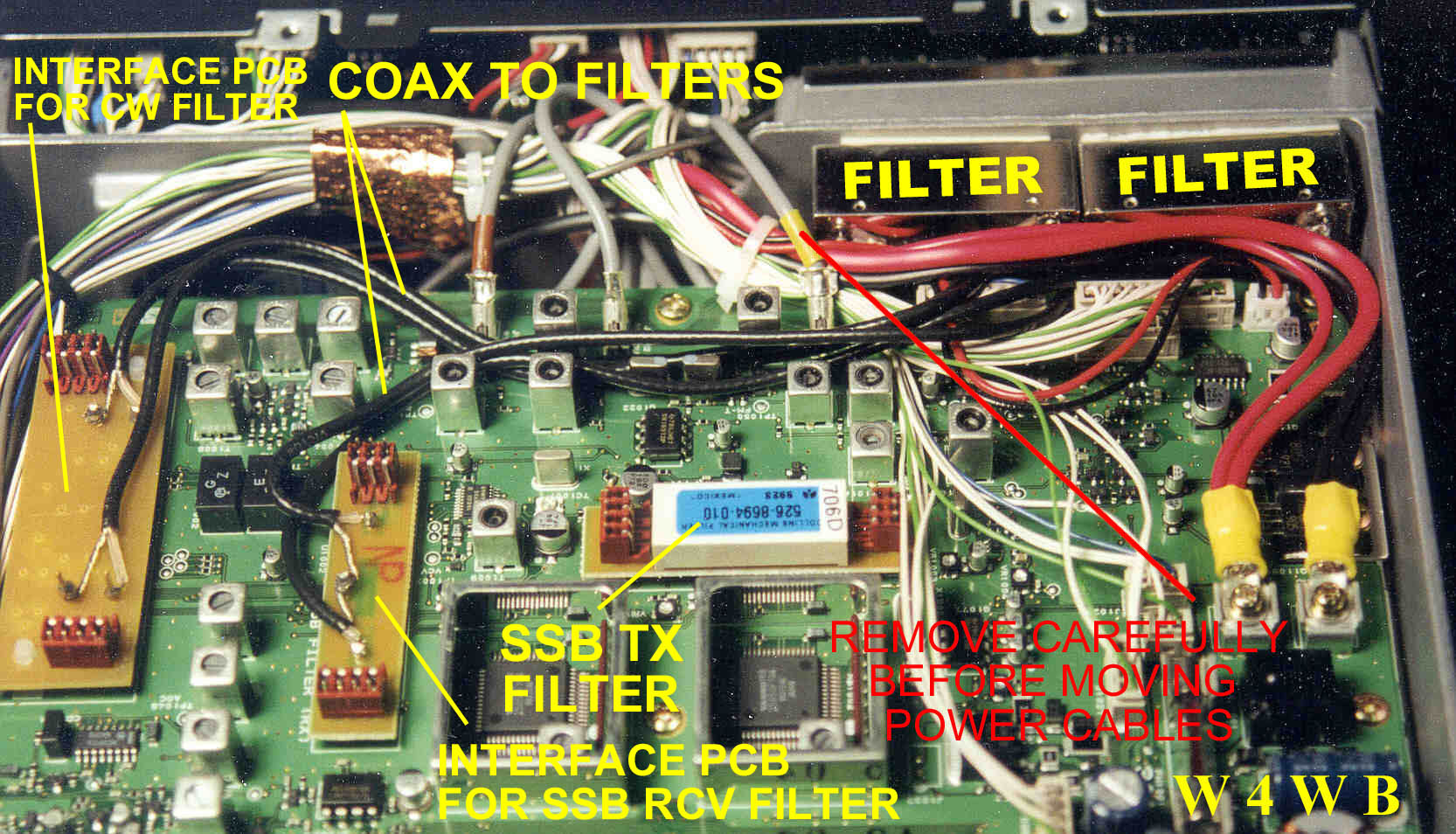
"Installation was surprisingly easy, though tight. I unplugged the 3 coax cables (L to R, viewed from bottom,
color coded yellow, none, brown) coming from the front of the circuit board, and also the plug at position J1004,
so I'd have room to route the coax from the filters under the existing cable bundle. After installing the filters,
I also had to spread that large cable bundle around one of the IF transformer cans on the circuit board to be able
to comfortably fit the case bottom back on. BTW, this data is from a 9G serial number; your color codes may vary.
All I can say is, wow."
20Jan00 Update: The following text is taken from the Inrad catalog (which is an excellent tutorial on filters)
and may help someone decide whether to get the 1.8 kHz crystal filter or the 2.1 kHz filter.
"The 2.4 kHz filters are used to improve selectivity in radios which are normally supplied with a 2.7 kHz filter. The improvement is modest, but it is noticeable and fidelity is compromised little.
"For most general operating conditions, the 2.1 kHz bandwidth is ideal.
It is the best compromise between intelligiblity and qrm reduction. It's a good
bandwidth for dxing and contesting as well as rag chewing in crowded bands.
The 1.8 kHz filters are most useful for contesting where conditions are severe."
08 October 2002 Update:
Barry W4WB sent in a photo which shows you how to properly route the cables,
etc. for the installation of the INRAD filters. You can take a look at the photo
>> here << !
Update: A ham (who will remain unidentified) reports that he smoked his ATAS circuitry in the FT-847 after he removed the ATAS-100 antenna and put a wattmeter in line that had a DC ground on the coax. He was sure he switched the Menu #31 setting back to Tuner before removing the ATAS-100, and turned the radio back on. After a little while, smoke came out the back of the rig and the ATAS no longer worked. The same ham reports that the ATAS-100 instructions caution against allowing a DC ground to exist when in the Ant setting (instead of Tuner) of Menu #31. I could find no warning about this in the Operating Manual for the FT-847. A word to the wise. Note that this is a separate issue from turning on the mast-mounted preamps in Menus #29 and #30; on these the manual is clear not to present a DC ground to the rig's jacks.
Update 21Feb00: Lee Devlin, K0LEE, has implemented a FT-100
FAQs page which contains additional information on installing and using the ATAS-100 motorized antenna.
[Return to Main Menu]