OTT-847 interface for LDG antenna tuners
W4RT Electronics came up with a new interface
to connect to LDG antenna tuners. With this interface it is possible to use
the CAT software "FT847-SuperControl" to automatically engage a tuning
process with LDG antenna tuners when the transceivers frequency has been changed
(No-Touch Tune). Click >> here << to see
a picture of the OTT-847 interface.
As we all know, tuning the FT-847 with other than the Yaesu FC-20 Tuner is simply
annoying at best. In addition, the FC-20 has a poor tuning range (3:1 SWR) although
it is nicely integrated into the operation of the FT-847. Oh, did I mention
that one can't use CAT when using the FC-20? This message is to announce that
W4RT Electronics and SuperControl Amateur Radio Software have worked together
to solve the problems of no CAT and to allow autotuning with tuners having a
broad tuning range (10:1 SWR)! During the past two years, W4RT Electronics has
developed One-Touch Tune Modules for the FT-100/D, FT-817, FT-857, and FT-897
radios, which allow them to be easily used with third-party tuners, particularly
LDG Electronics autotuners. W4RT and LDG are affiliated companies. Unlike the
other radios, the FT-847 has been a particularly challenging radio for which
to develop a One-Touch Tune module. The following several paragraphs will describe
the new system.
The first new feature of FT847-SuperControl is the support for the new W4RT
Electronics One-Touch Tune (OTT-847) interface. With this interface it is possible
to automatically control antenna autotuners from LDG Electronics. At present,
the LDG autotuners AT-11MP, RT-11, and AT-1000 are supported, as will be future
models. The OTT-847 connects to either the 9-pin DIN connector on the FT-847
or your computer port used to control the FT-847 by CAT. The OTT-847 has an
internal null modem, a cable to connect to the FT-847, and a cable to connect
to the LDG tuner. FT847-SuperControl now offers a "One-Touch Tune"
function where you can start a tuning process on a connected LDG autotuner simply
by pushing a button on the computer monitor screen. The software will command
the OTT-847 interface and will change the FT-847 mode to generate a stable carrier
needed for the tuning process. After the successful tuning, the original operating
mode will be restored and you can start operating on the new frequency (typically
1-3 seconds).
Of course, the FT847-SuperControl is able to detect when the Tune button on
the LDG autotuner is depressed. In this case, the software will also command
the OTT-847 and the FT-847 to produce a proper signal for the tuning process.
Now if that isn't great enough, then give the "No-Touch Tune" function,
which is also available in the software, a try! In this mode, FT847-SuperControl
automatically detects a frequency change of the transceiver. If the frequency
change exceeds a user predefined step value, the software will tell the OTT-847
interface and the LDG tuner to start the tuning process automatically. In other
words, you don't have to push a button on the screen or the tuner to have the
LDG tuner perform a match at a desired frequency. This will be done automatically.
In-band QSY retuning takes typically about a second while band changes may take
several seconds.
Supported LDG tuners are:
AT-11MP, RT-11 and AT-1000 (as will be future models)
[Return to Main Menu]
AT-11 Auto tuner
Considering the limitations of using the CAT feature and the FC-20 with the
radio, some owners have opted to purchase the AT-11 auto tuner from LDG
Electronics. This is available in either a kit or assembled format and does
not suffer from the CAT/FC-20 limitations.
Update 08Jun00: The AT-11 tuner has undergone some major revisions and is now the AT-11MP model. It has
some new features (e.g., meters, remote unit) that seem to be very nice.
[Return to Main Menu]
Modifications for the FT-847
Perhaps due to the relatively high cost of the radio, people do not appear to have delved too deeply into it and
there are not many modifications available for it. There is the usual set of solder pads that are used to define
the "country" for the radio. The company sets these depending on what country the radio will be sold
in. Caution: modifying your radio in this manner may lead to the company not honoring the warranty. You can get
some excellent information on the mods from Colin G1IVG's web page at http://personales.jet.es/colinlowe/index.htm.
Also, see Opening up transmit range, below.
[Return to Main Menu]
Opening up transmit range
There is a set of six solder pads inside the radio that appear to give each radio it's "country identity"
and to perhaps do other things. People have found that by changing the configuration of these solder pads, one
can open up the transmit range of the radio. One caution: when the transmit range is opened to the full RX range
of the radio, it is possible to transmit in the 36 MHz range which some say can destroy the RF power transistors.
One good location showing how to make the mod is Colin Lowe's (G1IVG) web page, http://personales.jet.es/colinlowe/index.htm.
According to Colin, after doing his modification, the following transmit frequencies are available:
Band Min TX freq. Max TX freq.
H.F.
1.8MHz 37MHz
VHF (A) 37MHz
76MHz
VHF (B) 137MHz
174MHz
UHF 410MHz
470MHz
DO NOT TRANSMIT OUT OF BAND, PLEASE!
Keep in mind that the FT-847 is not marketed as a "wide-band" receive (or TX!) radio, and it is not.
Because of it's design, its performance is optimized for the transmit ranges that it comes with and it will not
open up as widely as, say, the FT-50R or VX-1R and other HTs. One possibly undesirable feature of modifying the
country designation is that the radio will no longer "know" what country it is set for, so the automatic
repeater shift (ARS) feature will be lost on FM.
Also keep in mind that the transmit power will drop off quickly when transmitting outside the normal ham bands
(which you should not be doing anyway unless you're driving a transverter). Also keep in mind that many of the
antennas typically used on a radio of this type are not wide-band anyway.
Update 20Mar00: There is a wide variety of jumper settings that you can make that affect RX, TX, or both
at once. Colin's page has a nice table that shows all the combinations of jumper settings and the RX and TX ranges
for each setting of the blobs. Take a look. This information should be of interest to European hams, where the
RX range is limited depending on the country in which the radio is marketed.
[Return to Main Menu]
Loss of ARS after TX Modification
If you do the modification to open up the transmit range, you will find that the Automatic
Repeater Shift (ARS) feature no longer works. This is apparently due to the fact that the ARS is country-specific.
You might ask why it wouldn't work on the new country's ARS pattern that you set the rig to. Don't know why. Perhaps
the modifications that people have found change something besides just the country setting.
[Return to Main Menu]
Separate Receive and Transmit Lines on 2m & 70cm
Peter OZ1PIF has made a modification that will separate the RX and TX lines
for 2m and 70cm. By adding two additional antenna jacks on the rear and by making
a small mod inside, Peter has enabled a separate RX port for each of the two
bands. This will facilitate adding pre-amps and interfacing amplifiers. You
can see some detailed pictures of his modification by checking out his web site,
http://www.frenning.dk/oz1pif.htm.
[Return to Main Menu]
Cat Control Operations
The FT-847 seems to have a set of unique op codes for CAT control. Yaesu in general, does not appear to have a
consistent set of codes for any of their radios (unlike Kenwood for example).
Given that, you can't select another radio in a software offering that doesn't show the FT-847 specifically.
The original design for the FT-847 did not include two-way CAT control operations for frequency and mode. You could
use your PC to give commands to the radio, but the radio could not report back any frequency or mode information
to the PC. Many, including QST, complained about this shortfall, and the company modified the firmware in the radio
to enable two-way CAT control operations for frequency and mode. Starting with serial number 8G05xxxx (see the
explanation of serial numbers here), two-way CAT control is standard.
In a real credit to Yaesu, it offered to upgrade any earlier model radios to the two-way CAT control, so many of
the earlier models have two-way CAT control. If you're buying a used FT-847, ask if it has been upgraded.
The CAT control for the FT-847 does not convey the final digit (i.e., the ones digit) under any circumstances,
so no external software can ever resolve any frequency better than 10 Hz. The FT-847 itself resolves to 1 Hz.
[Return to Main Menu]
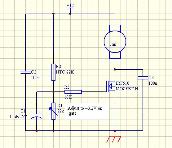
Fan speed controller (thermostatic)
by Peter, OZ1PIF
For several years i have mostly used my Yaesu FT-847 with the annoying rear fan
disconnected, but lately I have noticed that the radio gets quite warm to the
touch, and noted some frequency drift when running high-dutycycle modes like WSJT
for extended (hours!) periods of time. I cannot accept the obvious solution -
letting the fan run, when not really needed most of the time! The solution: Thermostatic
control.
The solution developed can be applied to any low-voltage DC-driven fan, but
here it's been implemented specifically for the FT-847. (Thanks to Thomas, OZ2CPU
for original circuit idea)
(click for circuitry picture)
None of the component values are critical, and any N-channel MOSFET with a
reasonably low on-resistance can be used. I selected the IRF510 because I had
a supply already in my component drawer, and because it's cheap (~ 0.3$)
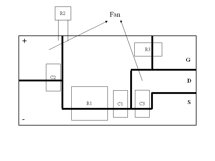
(click for PCB picture)
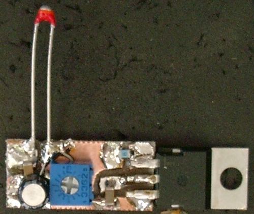
(click for fan controller picture)
The circuit has been mounted on a hand milled PCB (size 10x20mm). In the picture
the NTC resistor has just been soldered on with long leads for testing purposes.
Where available SMD components have been used.
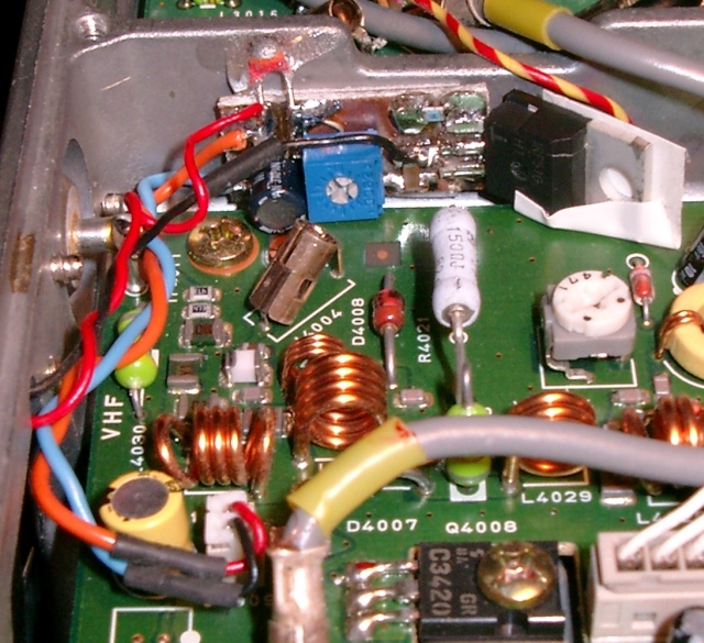
(click for fan controller in place picture)
Here the Fan controller has been mounted in the VHF/UHF PA compartment of the
FT-847, note that the 144MHz cable to the Rx side has been removed for clarity.
The MOSFET has been wrapped with a small piece of electrians tape to make sure
that there is no contact between the Drain flange and the PA board. The controller
PCB itself has been fastened to the chassis with a small piece of adhesive foam.
The lead from the fan to the connector has been cut, the red lead to the fan
soldered to the + 12V pad and the black the the Drain pad on the controller.
The rest of the leads, leaving the connector has been taken to the + and - 12V
pads on the controller using two approx. 5 cm long leads. The NTC resistor has
been glued to the chassis for positive thermal contact.
Final adjusment for approx. 3.2V on the Gate finishes the job.
Now a temperature increase of 5-6 degrees centigrade will cause the fan to
start, and it'll continue to run at required speed until everything has cooled
down sufficiently. Note that the supply voltage for the fan drops about 1.5V
when transmitting, causing the fan to increase speed in Rx mode (until subsiding
with temperature decrease)
[Return to Main Menu]
Polling Codes for Frequency & Mode
The FT-847, as originally delivered, could not poll the radio for frequency and mode information. This was added
beginning with the 8G05 production runs. The Operating Manual does not show the codes for polling the radio. They
are as follows.
To query the radio: Send a 5 byte sequence as follows: * * * * P1
Where *=Any value and P1=03 for Main VFO, 13 for RX Sat VFO, and 23 for TX Sat VFO.
Note that you cannot query the sub-VFO, nor can you swap VFOs via software.
The rig will return a 5 byte data sequence: D1 D2 D3 D4 D5
Where D1 contains the 100 MHz and 10MHz digits (in Hex format), D2 contains 1 MHz and 100 kHz digits, D3 contains
10 kHz and 1kHz digits, D4 contains 100 Hz and 10 Hz digits, and D5 contains mode data as follows: 00=LSB, 01=USB,
02=CW, 03=CW-R, 04=AM, 08=FM, 82=CW(N), 83=CW(N)-R, 84=AM(N), and 88=FM(N).
Example: 14 69 40 00 08 = 146.940.00, FM mode.
Note that you cannot poll or set the 1 Hz digit.
Page 91 in the manual describes sending frequency & mode to the radio; decoding it is similar.
[Return to Main Menu]
Raspy or FMing audio reports on SSB
There have been a number of postings like the following: "I have been getting signal reports that my FT-847
sounds very raspy and from what everyone is telling me it sounds like it is trying to FM on me when I am on USB.
Seems to do it on all bands. Tried (3) different microphones including my Heil. Tried adjusting menus for treble
and bass but nothing helps."
Replies have suggested that the problem was cured by moving the radio further away from the power supply. Apparently
this is a problem with large linear supplies. My switching 30 amp supply is a foot away and I have no problems
like this.
[Return to Main Menu]
Noise Blanker
In mid-June 1999, there were a number of postings regarding the noise blanker (NB) and its effectiveness. It was
a mixed bag of experiences, however, where a couple could not find that it made any difference at all, and a few
more said it was very effective. There was also some confusion as to what a noise blanker should cancel. The Operating
Manual, on p. 21, says that it "may help reduce many different types of man-made impulse noise (but not atmospherics)."
The DSP and Noise Reduction (NR), on the other hand, got high praise for effectiveness.
[Return to Main Menu]
Special & Hidden Menus
There are two special menus (at least), on the FT-847. One, documented in the Operating Manual, is accessed by
changing Menu #42 EXTEND to ON. This activates menu choices 90 through 96. Since the features are discussed in
the manual, I won't say any more here.
The other hidden menu is the Alignment Menu. The Operating Manual does not discuss this menu, but the Technical
Supplement (the "service manual") does. To access this menu, you need the standard
mike with the UP, DOWN, and FAST buttons. Hold down these three buttons simultaneously and turn on the radio using
the power switch. This will place you into the alignment menu. Doing this does not cause a reset of your
radio.
The FIRST thing to do after accessing the menu is to use the Sub-Tune knob to step through each setting and write
down the values shown. There are 25 different variables that are identified by a mnemonic. The values are shown
where the channel number normally displays on the display, and they are in hexadecimal format. The RX-GAIN and
TX-GAIN parameters are band-specific, so you should write down the values for each band (each HF band, 6m, VHF,
UHF).
On TX-GAIN the Technical Supplement has you do separate adjustments for 160m, 20m, 10m, 6m, 2m, and 70 cm. On RX-GAIN,
it has you adjust 80m, 20m, 10m, 6m, 2m, and 70 cm.
There are two ways you can use the alignment menu. The first is to use the proper methods to establish the correct
values. The second is to manually change the values for one or more parameters. Both are discussed below. By the
way, not all the alignment steps for the radio can be done from the menu.
Thanks to David G7LMT for providing the correct information for the discussion below.
Also, Scott VE3SCP has done a full alignment of the rig and has some insights into the process and the Technical
Supplement. He has offered to elmer people with questions. You can email Scott by clicking
here.
Using test gear to establish and set the proper values (as described in the Technical Supplement)
1. Set up the machine as instructed in the Technical Supplement.
2. Go into alignment menu by pressing the UP, DOWN, and FAST keys on the stock microphone while turning the rig
on with the power switch.
3. Use the SUB-TUNE knob to select the appropriate parameter.
4. Inject the appropriate signal into the appropriate port as instructed in the Technical Supplement. Press MCK/W
to allow the resulting value to be logged onto the display. By pressing MCK/W, you are "taking the measurement."
The numeric value, in hex format, is shown where the channel number usually shows on the display.
5. To set another parameter, Return to Step 3, or go to step 6 if you're finished.
6. To retain ("save") the resulting values for all the changes you have made to the system's memory,
you then press the MENU button. This returns you to normal operation. NOTE: If you do NOT want to save the changes
you've made, press POWER off without pressing the MENU button; this abandons the changes.
Manually setting the value for one or more parameters
If you want to manually set the value for a parameter, as opposed to using the test equipment as described above,
you can do this as follows:
1. Hold down UP, FAST, and DOWN buttons while turning the rig on.
2. Use the SUB-TUNE knob to select the parameter you want to adjust.
3. Turn the MEM/VFO CH knob to manually change the value that is shown. This knob will increase or decrease the
value depending on which way you turn it.
4. To set another parameter, return to Step 2, or go to Step 5 if finished.
5. To memorize ("store") the new value you just set manually, press the MENU key to memorize it. NOTE:
If you want to abandon the changes you have made, press the POWER switch instead of the MENU key.
At least one of the menu parameters has two parameters; you get to the second one by pressing the A-B VFO swap
button.
Now, I don't know what all of these settings do. The names are cryptic, to say the least, and the Technical Supplement
doesn't help too much. What I do know is that a couple of hams have adjusted the DISC-L and DISC-H settings to
bring their discriminator to the center setting. The other settings do not seem to do anything magic (like more
power!); rather they set meters, RX gain, TX gain, carrier point adjustment, SWR "meter," etc. It looks
like you can "undo" changes you have made if you want to return to the factory settings, but only if
you've written them down! You're on your own, though! I reiterate my recommendation to get the Technical Supplement
if you want to experiment with these settings.
Everyone who plays around with these settings is encouraged to submit posts explaining what he or she did and the
results so the rest of us can learn from the experiments.
[Return to Main Menu]
Reports on the Alignment Menu
NOTE: Please read the discussion on Hidden Menus before reading the following reports
from others! Read especially the section titled "Manually Setting the Value for One or More Parameters."
These reports may not have been confirmed by others or me.
Adjusting the discriminator setting
Jim W4LC reported that he manually adjusted the DISC-L alignment setting slightly (one digit) and this caused his
discriminator setting to show correctly on his "meter."
David G7LMT reported that he adjusted his DISC-H alignment setting by five digits to bring the discriminator to
the correct setting.
Update 11/26/99: Chuck AA6G reported his results on adjusting the FM discriminator reading. This report
is interesting because he used the menu to customize the discriminator to show deviation over the greater range
than the stock settings. I'll reproduce his results verbatim.
"I was reading the FAQ and decided to adjust my discrinator setting since it was a little off too. I used
an HP-8640B as the signal generator. It seemed as though the DISC-L and DISC-H menu items should be the low and
high adjustments and indeed they appear to work that way. I found the total range of my meter to be less than 2KHz
and I wanted a little more range.
I was able to get +/-5KHz by setting DISC-L to 21 and DISC-H to 38. My meter now moves off center one segment at
about +/-500Hz. The tradeoff is less sensitivity to a small frequency change but a greater range. I suspect you
[could] get +/-10KHz if you wanted it.
"You can perform this adjustment with an on-the-air signal if you have one you trust to be accurate.
Simply tune above and below the signal the amount you want and adjust the menu item so the meter just
reaches the limits."
Adjusting the Transmit Gain - PLEASE READ ENTIRE DISCUSSION BEFORE CHANGING ANYTHING!
I recently used the alignment menu to adjust my TX-GAIN to see what would happen. First, though, I wrote down what
the setting was before doing anything. There are actually six different TX-GAIN settings: 70cm, 2m, 6m, 10m, 20m,
and 160m. You will need to tune your rig to the band you want to adjust, then go into the alignment menu by holding
down the three buttons on your stock mike while turning the rig on. Use the Sub-Tune knob to turn to TX-GAIN. Write
down the setting, and remember that it's only for the band you're on. Now, you can use the MEM/VFO CH
knob to change the TX-GAIN value. Mine was at 8F to begin with, and I was working on the 2m band.
As I reduced the values, nothing happened until I got down to about 48. Between 48 and about 41, the output power
began to drop off quite a bit. By 40, I could not measure any output on my watt meter. I then returned the setting
to 8F and things were back to normal. I did not try increasing the value beyond 8F. Even after changing
this value, you can use the RF PWR knob to reduce the power below the maximum value.
You can actually check things as you go. After turning the MEM/VFO CH knob, you can still change modes and key
the rig with a CW carrier. This way, you can check the resulting output instantly without having to return to normal
operations. Once you have a setting you want, press the MENU button to return to normal operations. You can return
to the alignment menu as often as you want to change things some more.
This ability would seem to be particularly helpful for hams running amps that have, say, a 10 watt input. If you're
always using the amp, you could adjust the TX-GAIN to limit output and protect your amplifier. There are some tradeoffs
on doing these adjustments. Please see the discussion on Limiting Maximum Output Power for
an explanation from Yaesu.
Note: Two of us have stumbled onto something you should know about. We think that, if you are fooling around with
TX-GAIN and you change bands with the band switches while you are in the alignment menu, it may transfer
the TX-GAIN setting to the register for the band you just switched to. All the more reason to write down all the
values before you begin fooling around with the Alignment Menu.
Update 20Aug00: Another way to control power output of your FT-847 is by using the ALC control circuit.
Click here to read about how to use ALC to control power output.
[Return to Main Menu]
Typical Alignment Menu Settings
I include here my alignment menu settings in case it might help someone with a problem. I don't think I've changed
any of these from what the rig came with (but I might have!). I'm sure your settings will be somewhat different
from these, so this information should be used for comparisons only. There are 25 different settings and some of
those have multiple values, depending on what band you're on. I know that at least one has two values that are
accessed by using the A-B swap button. Also, I don't know what many of these do!
FM-S1 58
FM-FULL 89
RX-GAIN 75(160-30), 93(20-15), A2(12-10), 6B(6m), 43(2m), 47(.7m)
SQL-TH-L 5A
SQL-TI-L 00
DISC-L 24
DISC-H 30
SSB-S1 DD
SSB-S9 5E
SSB-FULL 26
SFT-CTR 7F
RXC-PNT 00
TXC-USB FE
TXC-LSB FA
PWR-100W 91
PWR-50W 62
PWR-20W 3E
PWR-10W 2B
ALC-1 06
ALC-9 2F
TX-GAIN AF(160-30), A8(20-10), 8F(6-2), 64(.7m)
SWR 1.5 12
SWR 3.0 3E
ALL-CLR 00
DSP-PASS 00
[Return to Main Menu]