15Jul01
AM Transmissions
There have been some postings discussing poor audio on AM. Stuart G1IDE wrote to say that a member of his club did some digging into the problem and got confirmation from Yaesu UK that the Operating Manual is incorrect on p. 58.
According to the manual, to set up AM for proper transmitting, you need to tune your radio, put it in AM mode, reduce the mike gain to nothing, and then turn on your transmitter with no modulation. Adjust the output power with the RF PWR knob until you show 33% of the rated output power for the band you're on. This is 33 watts for HF and 6m, and 16.5 watts for VHF/UHF.
Then, the manual says to advance the Mike Gain from nothing while speaking in a normal voice until you see a slight downward deflection in the power out on voice peaks. The "downward" is the error. It should say to advance the Mike Gain while speaking until you see a slight UPWARD deflection of the output power on voice peaks. Stuart reports that once his club member adjusted the rig as described here, his audio has been great.
Receiver overload from nearby commercial transmitters
Jim G7UTB reports that he lives nearby a large commercial tower and was having trouble preventing his radios from being overloaded, particularly when he was using an extermal preamp. I thought his comments on other popular radios, in addition to the FT-847, might be interesting. His comments follow:
"I have tried other radios at this location, ie IC-706 I could NOT use this radio AT ALL on 6M 2m & 70cm. Even with the antenna sockets grounded out it was S9 pagers. I spoke to Icom UK about this and NO ONE replied to me despite several phone calls. I have also tried the IC-820H It was pretty good but even with a DCI 2M band pass filter infront of it had problems. The next Rig was the FT-736r was ok but I could not use an external Pre-amp. The FT-847 in my opinion is near perfect on its own for out of band sig rejection. I can hear pager break through on occasion but it is frequency specific (ie qsy up or down and it's gone). With the DCI filter in line I might hear some but that is usually if it has been or is raining and even then it does not happen all the time. I think that I am going to have to accept that I live in a high RF (use) area and maybe build my self a suitable pre-amp for use on 2M."
Update 08Jun00: Howard G6LBV reported on this issue as well. "I too have problems with pager overload,
which peaks at +20dBm on 153MHz. Also I have trunk radio at +10dBm on 440.5MHz. Neither of these have ever affected
the operation of my FT847 at all when running barefoot. I have both 2m and 70cm SSB Electronics preamps at the
mast which are both slightly affected by intermod from the above. For satellite work they're nearly essential.
"I can't comment on the TS790 or IC821, but I can comment about other radios. In comparison to the FT847,
any other units I've tried on the same antenna/coax setup (eg AR5000, IC706-IIG) suffer _really_ badly to the point
where they're not usable at all sometimes, especially on 2m, without attenuation, or alternatively a bandpass filter
such as the DCI units.
"However, I would say that as I don't need a filter to run the FT847 barefoot, you can say from above that
you get a pretty good dynamic range at 2m on the FT847."
Lee Devlin, K0LEE, has a FAQs page specific to the FT-100, including links to other FT-100 resources and some photos of ATAS-100 and FT-100 installations. It's a good site. Find it at http://members.home.com/k0lee/ft100faq.html.
In the U.S.A., you can reach Yaesu as follows:
(These are new email addresses as of 25Feb00)
Amateur Technical Support: amateurtech@yaesuusa.com
For parts: yaesuparts@yaesuusa.com
For sales: amateursales@yaesuusa.com
By postal mail: Yaesu U.S.A., 17210 Edwards Rd., Cerritos, CA 90703, U.S.A.
Update 26May2002: Yaesu Contacts
Attention: Here is the new contact information for Yaesu as of April, 2002:
VERTEX STANDARD US HEADQUARTERS
10900 Walker Street
Cypress, CA 90630
Phone: 714-827-7600
Fax: 714-827-8100
EMAIL ADDRESSES:
Amateur Sales: amateursales@vxstdusa.com
Amateur Tech Support: amateurtech@vxstdusa.com
Amateur Customer Service: customerservice@vxstdusa.com
Parts: yaesuparts@vxstdusa.com
International contact information can be found at:
http://www.yaesu.com/amateur/contact.html
Replacing or Fixing Broken Power Switch - Updated 15Jul01
There have been a number of reports of failed power switches, so when mine got a little mechanical "hitch" in it, I decided to see what replacing the switch would involve. Having looked at it all, I thought users might like to read about how to go about replacing the switch. Not too hard, but not too easy, either.
First, if you're not a tinkering type of ham, just double box the unit if the switch breaks, and send it to Yaesu for service. Otherwise, the tinkerer's steps follow. In all cases, left and right refer to direction with the front of the radio facing you, either right side up or down. NOTE: If you do not have experience in removing "multiple pin with plated through holes" types of components, you might rather leave this work to others. (But see Update 01Feb01 below)
The "front panel" consists of a three part sandwich: the "black plastic facepiece," a "steel chassis," and the "circuit board assembly," in that order from front to rear. The circuit board assembly holds all the rotary controls and switches for the rig. The rotary encoder itself is attached to the steel chassis. First we'll remove the black plastic facepiece which will allow you to remove and work on the headphone jack, if you need to. Then, we'll remove the circuit board assembly, leaving the steel chassis still attached to the rig. Now you can work on the power switch.
Update 01Feb01: John N3ZKK has written some instructions that you can follow to replace ONLY the guts of the switch, instead of unsoldering and replacing the complete switch. The directions below direct you to John's explanation of how to replace the guts, or you can click here to go there immediately. Be sure to come back here for front panel disassembly directions.
Update 21Mar01: Johannes OH6HFX reports that he got fingerprints on his LCD display after disassembling the front panel and that he could not remove them completely. So, you might want to cover the LCD display after exposing it in Step 5 below.
Also, thanks to Johannes for providing pictures of the disassembly. They are shown in the instructions.
| 1 | Remove both top and bottom case halves by removing 8 screws (2 in handle on right, two on left, two on front bottom, and two on the rear, one on top case and one on bottom. Put the case halves aside in a safe place. |
| 2. | Turn the rig over onto its top with the front panel facing you. In the shuttle jog ring is a slit you can now see. Look in there with a flashlight, rotate the VFO knob, and you'll see a tiny setscrew that holds the VFO knob in place. Use a small Allen wrench (1 mm; one fellow reported 1.5mm fit his knob, and 1/16" fit mine one time) and loosen the setscrew. Slide off the VFO knob. Pull off the shuttle jog ring. Leave the spring in there alone. |
| 3 | Remove the little black screw immediately above the shaft for the VFO knob. It's tiny. Turn the rig back over so it's right side up. |
| 4 | Turn all your knobs to their counterclockwise positions. Pull off all the knobs (but not the switch buttons!) from the rotary controls on the face of the rig. They just pull off. Remove the large nuts and flat washers from the RF Power, Squelch, AF, and DSP controls (4 in all). |
| 5 | You can now remove the black plastic faceplate of the rig by lifting gently on the molded hooks (3 on the top and two on the bottom) that hold the black plastic faceplate on to the steel chassis. Carefully lift the black plastic faceplate off the front of the radio. I had to "work" it a little. Do it gently to make sure you have removed everything (it's easy to forget something) holding the faceplate on. The buttons will stay attached to the faceplate, and the switches themselves will stay attached to the circuit board (which is attached to the steel chassis). Note: the LCD display is now no longer protected, so be careful you don't damage it. If you have a service manual, it might be helpful to look at the exploded picture of the rig, but you don't need it. Try not to touch the LCD display; in fact, it would be good to tape a cover over it. |
| 6 | Now, if you want, you can remove the headphone jack by sliding the C-shaped clamp off the front of it. See Step 8 for lowering the front panel to get the headphone jack out the back. |
| 7 | Carefully but firmly, pull off (they snap off and on) the switch caps from the Power and MOX switches Howard G6LVB reported breaking a shaft pulling the knobs off. Remove the three large gold colored nuts and flat washers from the remaining rotary controls (MEM/VFO, IF Shift, and Sub-tune). |
| 8 | The front of the rig can now be dropped down by removing two screws on the top of each side of the case. Loosen the two lower ones a little, but don't remove them. You will see a slot for the lower two screws. Slide the whole front of the radio towards you so it can swing down (the top of the panel comes down towards you). Make sure the two lower screws slide to the rear of the slot or the panel won't swing down freely. Swing the panel down, exposing the circuit board assembly on the back of the front panel. I usually find it handy to have the rig positioned near the edge of the work table so that the dropped down part is beyond the front edge of the table, approximately horizontal. Click for Photo. |
| 9 | If you are only working on the headphone jack, you don't need to go past this step. |
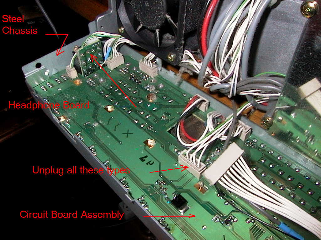
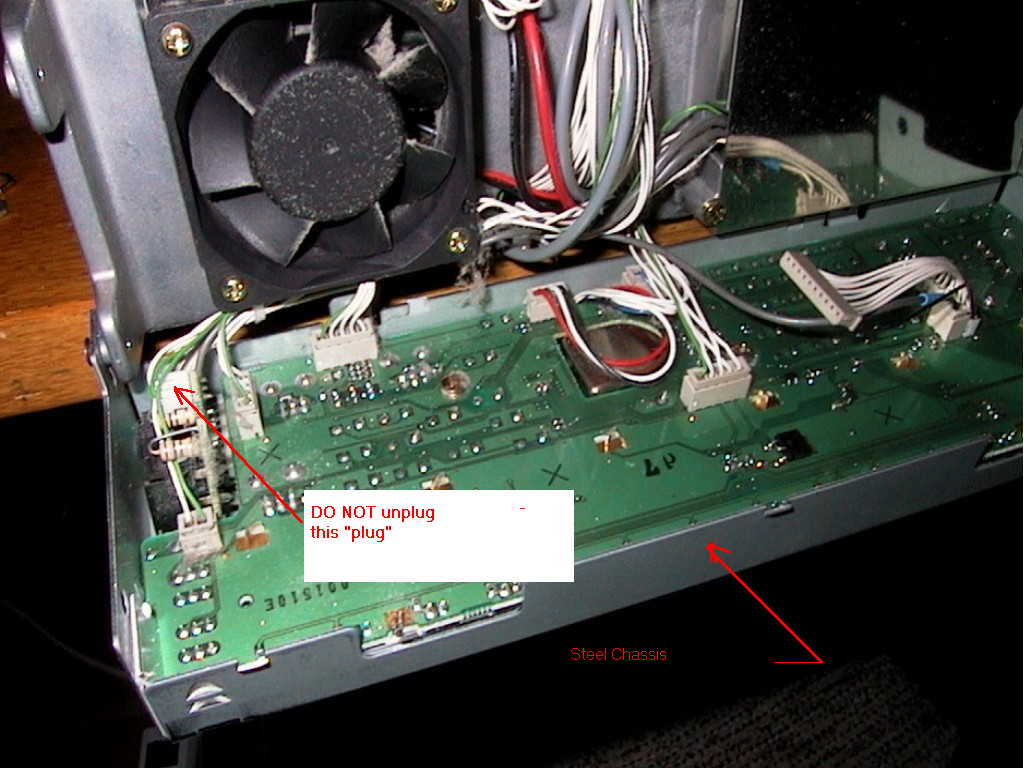
| 10 | Pull all the connectors off the jacks on the back of the circuit board assembly, except the one on the little circuit board that's mounted to the back of the phones jack. Click here to see a photo of the back of the circuit board assembly. I jockeyed each one from the side edges until they came off. (As you are doing this, be sure you don't damage the LCD panel.) Carefully cut the tie wrap that holds the wire bundle together on the left side of the panel. If you do not have the voice synthesizer, you will see a wire assembly attached to the circuit board assembly and just hanging in the air. You can leave this in place regardless. |
| 11 | Remove the three gold colored Phillips-head screws on the circuit board assembly on the back of the steel chassis. DO NOT straighten any of the bent metal tabs that hold the LCD display into the circuit board; leave them alone. |
| 11a | At this point, some units may have a small rectangular aluminum plate glued with sticky tape to the back of the assembly, near the headphone jack. You will need to remove this plate in order to proceed. Eddie G0EHV thinks it's a mechanical feature to keep the board from flexing if the Power or MOX switches are pressed too hard. It appears to have no electrical or RF purpose. Peter OZ1PIF reported that, on a trip, his aluminum plate fell loose, shorted a trace, and damaged the front panel circuit! |
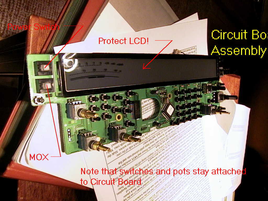
| 12 | The Power and MOX switches are still not exposed. Carefully lift the whole circuit board assembly from the back of the steel chassis. I had to "work" this, too. Keep in mind that all the rotary knob shafts are attached to the circuit board assembly and need to come out relatively straight. There are tabs on the steel chassis that help hold the circuit board assembly in place; just ease those out of the way so the circuit board assembly can slide off the steel chassis. The encoder will stay in place on the steel chassis. NOTE: You may find that you will need to remove the lower screws to free up the front panel. It's a bit of a three-hand affair, and there are some cables that will stay attached between the panel and the radio. Click here for a photo of circuit board assembly after removal. |
| 12a | NOTE: At this point you can, if you want, replace only the "innards" of the failed switch without having to unsolder the old switch. Click here to go to John N3ZKK's instructions for doing this. Those nervous about the solder work may find this method easier to accomplish. |
| 13 | Now the Power and MOX switches are exposed, and you can unsolder and remove it or them. The switches seem to fail in two ways: contact burns and mechanical failure of the latch. Gary N5IXI (his were burned) said he simply flipped the power switch (or the internal piece) over and used the spare set of pins. I guess it will depend on how your switch fails. I suggest getting a new switch instead. They only cost $1.88 from Yaesu. |
| 14 | Unsoldering the switch requires proper equipment and attention to detail. Some sort of desoldering equipment is needed, say solder wick and/or a heated solder sucker. Be careful not to melt the jack next to the switch and not to lift the traces. Although the holes are plated through, there are no contacts on the hidden side, only on the side you will unsolder from. If you have never removed components such as the switch, this is probably not the best place to learn (although some would have it no other way). Be careful of your LCD screen when you're working on the back side of the circuit board. |
| 15 | Reassembly is the opposite of removal. But, before reassembling, read below the table for some suggestions for things to do while you've got everything apart. |
| 16 | Put the circuit board assembly back in from the rear, making sure you don't pinch the wires going to the left side of the board or the encoder wires in the bottom center of the board. Pop the board into place, making sure the switches are all going through the holes (in the steel chassis) intended for them. Install the three screws that hold the circuit board assembly to the steel chassis. Reinstall three large flat washers and the gold colored nuts on the MEM/VFO, IF Shift, and Sub-tune knobs. Tighten the nuts. |
| 17 | Flip up the front panel and secure it with the four edge screws. Make sure you push the bottom of the front panel in all the way before tightening the four screws. Snap the caps back on the Power and MOX switches and check that the switch action is OK. |
| 18 | Carefully slide the black plastic facepiece into place, so the molded parts snap into place on the edge of the steel chassis. Check the switch action for all the knobs to make sure they're engaged with the switches on the circuit board assembly. Be especially mindful that the Clarifier and the Tune switch caps don't get dislodged. |
| 19 | Reinstall the little black screw that goes above the VFO shaft. Slide the shuttle jog ring back on. Put your Allen wrench in the screw for the main VFO knob, then slide the knob and Allen wrench on the shaft and tighten down the VFO knob. |
| 20 | Reinstall the flat washers and silver colored nuts on the rest of the rotary switches (RF Power, Squelch, AF, and DSP). Push all the knobs back on. The "ring" type knobs that go on two knob controls can be put on many different ways, so make sure you get the white lines where you want them. Reinstall the outside covers for the rig (bottom has to go on first) and secure with the eight screws. |
While you've got the radio apart, now is a good time to do some other housekeeping. First, you can slide off the metal clip that holds the headphone jack in place, and remove the jack and the circuit board attached to it. It comes out to the rear. This makes it very easy to change the resistors for headphone balancing. I had changed my resistors with everything installed, so I just inspected my work, now that I could easily see it. You can work on the headphone assembly after you have removed only the black plastic facepiece.
The other thing to do, if your rig is a year or more old, is to clean out the collection of dirt, lint, cat and dog hair, etc., that the fans have faithfully sucked into the rig. One way to do this is to remove the large metal panel that covers the circuitry on the top of the rig. Remove 12 screws and lift the cover off. On the left is the V/U power amp board. Mine was dusty and covered with junk. You can also now see both the fans to clean them. The PA board for HF is another layer down; I did not take any boards out to view that board, but it is probably a good idea to do it. (And report how to the bulletin board!)
You can pop out the button covers at this point and clean them if yours have become dirty. Thanks John N3ZKK for this suggestion.
It's also a good time to do a mod to the rear fan to quiet it down. I just soldered three diodes in line with the positive lead to drop the voltage a little. Others have put in resistors. Still others have simply unplugged the rear fan. Consider your cooling needs first, though.
If you're interested, this is the location to do the mod that adds a separate receive jack for VHF and UHF. Click here for a URL on that subject, complete with photos.
You're on your own here, and I can't guarantee things will go as well for you as they did for me, and I may have forgotten something in the steps above. If you want to learn how your radio works, and take care of it yourself, you really do need to take it apart and have a good look inside. With the schematic, you can understand what you are looking at much better.
Update 24/01/04:
Power switch part number ( tnx to ve2fsk)
Ref: S6501 Push Switch
MFR'S DESIG: SPH121A94
YAESU P/N: N4090086
Replacing Only the Internal Parts of the Power Switch
(New 01Feb01)
There are two basic types of switch failure, a mechanical one where the latching mechanism wears out, and an electrical one where carbon build up on the contacts causes the copper switch contacts to burn through. With either of these failures, you can replace only some switch parts instead of the complete switch. This requires you to take the switch apart and requires care to make sure it doesn't fly apart on you and spray some very small parts all over your shack. If you have had an electrical type of failure, you may be able to "rob" a new set of contacts from the MOX switch or even the other half of the Power switch, but a mechanical failure would require you to "rob" all the switch innards.
If you want to use this method, please first follow the instructions on disassembling the front panel until you get to the Note that refers you to this location. Click here to go to the front panel disassembly instructions.
John's instructions are a little complicated for me to follow, since I have not done this method, but if you follow John's directions as you disassemble the switch, it should make sense. Hey, if you mess up, you can then unsolder the old one!
John N3ZKK wrote:
Parts needed in addition to the initial disassembly of the front panel:
Skinny needle nose pliers (Tweezers may be substituted) Small Tweezers (pointed tip) Clean Level Work Surface
Note: Power and MOX switches are identical and use the same contact as the power switch with the other unused on
each. Caution: Switches are spring loaded. Hold firmly and work slowly.
Place the front panel flat on the work surface as you would if you wanted to operate it i.e. LCD up, power switch
to the top left. Protect the LCD. Finding a fingerprint or dog hair after getting it back together bites.
The switch is held together by a plastic shell that snaps onto the base at the bottom and top. The shell holds
(fixed) the 'clicker.' The shaft holds the contacts which will fall out if it is turned upside down. The base holds
soldered contacts and a loose spring.
To remove the shell use your Right hand to hold the shaft and the shell as if you expect them to pop out at you.
With the pliers push from the left to separate them, on the top and bottom of the shell so that it is un-clipped
from the base. Do not let go of the shell.
Drop the pliers and hold the shaft. Drop the pliers and hold the shaft. Do not let go. Do not let go.
Slowly remove all together--leaving the spring in the base of the switch--and place on a flat surface and put the
shell aside.
At this point if you do not have a new switch continue on. Otherwise open up the new switch and replace the parts
removed, including the shell, following the above procedure but with a third hand to hold the base.
No Replacement Part / Field Fix. (This fix is for those who don't have a spare switch to use)
The shaft has two very small gold plated contacts 'cradled' in its base.
One is used for making the on/off contact, the other is unused. MOX switch is the Same.
With the tweezers swap the contacts. They come out easily and will fall out if the shaft is turned on it's side.
An option at this point is to take the repaired power switch shaft and replace it with the MOX switch. This will
give the repair some longevity. The MOX uses the same single contact as the power switch.
Otherwise; Put the shaft back in, over the spring in the base, with the Left hand. Hold down firmly. Push the shell
back over the base with the Right hand. The shell will click back into place easily. Make sure both clips make.
Exercise the switch a couple of times to make sure all is well. Check the LCD for hairs and fingerprints.
Receive Range Limitations on Some Models
The FT-847 has various "country" identities, depending on where it is sold. The limits are in the RX and TX ranges allowed in various markets. The country identify is determined by a series of jumpers in the rig. In the USA, the radio is wide open on receive, and the TX is limited to the bands allowed in the USA. You can "do the mod" on the rig to open up the TX to everywhere it will receive. This is covered under Modifications for the FT-847, Opening Up the TX Range.
Radios sold in other countries have identities that appear to limit the RX range as well as the TX range. Apparently, the only way to open up the RX for these radios is to modify the country identity by removing or adding jumpers (or solder blobs) inside the rig. Colin G1IVG has an excellent web site that shows in a table all the various combinations of solder blobs and 0 ohm resistors and what RX and TX ranges are possible depending on the configuration. Click here to go to Colin's home page. There are combinations of jumper settings that will allow you to, say, open up the RX range, but not the TX range.
There are some who say you can void your warranty by changing the jumpers. I have not seen anything about this from Yaesu directly, so I don't know if this is true.
There seems to be some confusion whether the FT-847 is a "QSK" rig. It is not advertised as such.
I'm not sure there is a uniform definition of "full break-in" or QSK. On some radios, the RX and TX lines are diode switched and provide essentially no delay between RX and TX. The Elecraft K2 has QSK and, if you want, you can set the delay to 0 and hear the received signals between the elements of each character! The rig itself is totally silent when switching. That's QSK, for sure!
The FT-847 uses relays to switch between RX and TX, so any transition from one to the other involves one or more relays clicking. Menu #9 CW-DELAY allows you to adjust the delay from 10 ms up to 300 ms. I find the relays distracting and usually press the foot switch down when sending.
So, although the radio will switch pretty fast from RX to TX when sending CW, many will find the relay noise unacceptable at 10 ms timing.
There have been a few questions on the bulletin board about outboard amplifiers for the FT-847. This discussion reports on the experiences of three hams. Others are welcome to advise me on others.
Mike K8LH reported that he is using a "mint" SB-201 amplifier (with the factory 10 meter mod). He added the Harbach "Soft-Key" Mod ($15 ppd) and is very pleased with the results. Mike recommends not trying to key the amp directly from the FT-847; the Soft-Key is intended as a keying interface.
John VE7JDB says definitely do not try to key the SB-201 without an interface or you will destroy the FT-847's switching transistors. He also recommends the Harbach Softkey upgrade, available from http://www.harbach.com. John says he did not connect the ALC between the units; he controls the FT-847 output to avoid overdriving the amp.
Merle AA4QE reports that he uses an old AL-80A and it "works great" with the 847.
Update 07/02/00: John K4BNC reports on the Yaesu Quadra Amp: "I picked it because it had the features that were of most interest to me. One was including coverage of 6m. That allows me to replace 2 older tube amps (one HF and one 6M) with one unit. In addition it has dual inputs so I can connect both the 847 and my regular HF rig.
"I do not need or want the legal limit power of the Alpha (my beam isn't even rated for that kind of power) but there are times when a linear makes the difference in making a contact. I like going for a clean sweep in Phone SS and I have made 6M contacts with the old amp on CW that were at the noise level. The unit is quieter than the old tube amps and runs cooler without the constant filament drain. The built in tuner is a convenience but not a necessity if you have well matched antennas.
"However I would not like to use an amp that required an external tuner just to deal with a 2:1 SWR. Note that automatic band switching is not supported with the 847 since there is no band output; it only takes a few seconds to change bands using the frequency counter mode. You also get a built in peak and average digital power meter with both numeric and bar graph displays.
"One last nice feature of solid state amps. You can hear that rare one and have the amp on in 10 seconds while many tube amp require1 or 2 minutes to warm up the tubes. The Icom PW1 seems to have a similar set of specs but is about 20% higher in price. A no tune alpha is $6K.
"The Quadra no tune feature is really nice for HF contesting since if you fail to set the band you do not smoke anything - you just get an error message saying wrong frequency and automatically bypass the amp. One other reason for an amp that is personal to my situation. For many years I kept a schedule on 20M SSB with my Dad and often my Mom would join in. Given their age and loss of hearing it was important to have a strong signal.
"Bottom line Do you need such an amp Of course not! But once in a while
it is nice to buy that top of the line toy."
Update 24/01/04:
I wondered if anyone has connect FT847 to VL1000. My FT100MP is in for repair
and it sames a shame not to use the ATU in it. If anyone has could you email
me with the details as there is no band data out from the 847. I wrote about
this combination quite a while ago - it may still be posted in the FAQs. Since
there is no band out data from the 847, you need to use the F-SET function on
the amp. You press the button and then send a little carrier to the amp. The
amp has a built in frequency counter and will set itself to the proper frequency
range. (by John Siegel)